

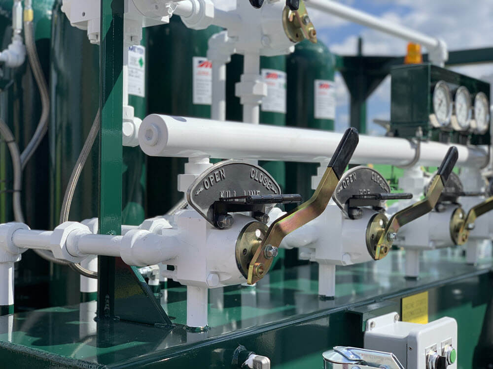
BOP Accumulator Manifold Design for Well Control
Review BOP accumulator manifold design factors and request custom API-16D accumulator guidance from MEYER.
BOP accumulator manifold design affects well control response by controlling how hydraulic pressure moves through the closing unit, how many leak paths exist, how quickly technicians can read gauges, and how clearly crews can operate labeled controls. MEYER builds BOP closing units with 2-inch seamless manifolds, heavy-duty gauge panels, visible operating labels, high-low bypass features, and serviceable piping layouts because manifold construction directly affects reliability, troubleshooting, and field service readiness.
A manifold is not just a collection of valves and fittings. It is the hydraulic routing center that connects stored energy, pump output, gauges, control valves, remote panels, and BOP function response. If the manifold has too many joints, unclear labels, poor gauge visibility, or hard-to-reach service points, the crew may lose time when the unit needs inspection, repair, or pressure confirmation. That is why we treat manifold layout as an engineering decision, not a cosmetic feature.
Our team reviews manifold design together with API-16D context, accumulator bottle capacity, electric or diesel power package selection, nitrogen backup, remote control requirements, arctic enclosure options, and aftermarket service planning. This article explains why seamless manifold construction matters, how gauge panels and high-low bypass logic support field operation, when welded or threaded layouts create service concerns, and how our Corpus Christi manufacturing and Odessa field service feedback shape custom accumulator builds.
Definition: BOP accumulator manifold design is the engineering layout of hydraulic valves, gauges, piping, bypasses, and control points inside a BOP accumulator unit. It is commonly used to route stored hydraulic energy to well control functions. For operators working across US shale basins and international markets, it helps by improving reliability, serviceability, and response clarity.
Request Custom Accumulator Guidance
Table of Contents
Manifold Engineering Fundamentals for BOP Accumulators
Seamless Manifold Construction and Leak-Point Reduction
High-Low Bypass, Gauge Panels, and Labeled Controls
Crow’s Foot Connections and Serviceable Piping Layout
Manifold Construction Comparison and Operational Value
Seamless Manifold vs Welded Piping vs Threaded Assembly Table
Field Service, Inspection, and Maintenance Use Cases
Regional Manufacturing and Field Service Feedback
Technical Deep Dive: Why Fewer Joints Matter in High-Pressure Hydraulic Control Systems
Forgotten Specs: Gauge Visibility, Labeling, and Technician Access During Troubleshooting
Frequently Asked Questions About BOP Accumulator Manifold Design
Manifold Engineering Fundamentals for BOP Accumulators
Key Takeaway: A well-designed BOP accumulator manifold reduces leak potential, improves pressure visibility, supports clearer control logic, and makes field service faster under well control conditions.

Seamless Manifold Construction and Leak-Point Reduction
Seamless manifold construction matters because every joint, thread, weld, and connection can become a potential inspection point or leak path in a high-pressure hydraulic control system. We use 2-inch seamless manifolds in our BOP accumulator and well control systems, with no joints, threads, or welds in that manifold construction, to reduce leak potential, improve structural integrity, and support easier replacement when service is required.
The manifold has to carry hydraulic pressure predictably from the accumulator and pump package to the controls that operate BOP functions. If pressure routing is restricted, unclear, or built with too many leak paths, the unit becomes harder to service and harder to trust. That is especially important when the accumulator is supporting land drilling, offshore operations, workover rigs, or rental fleet use where downtime affects more than one crew.
When we review manifold construction, our technicians focus on practical field questions:
- How many joints, threaded points, welds, and fittings does the hydraulic path include?
- Can the manifold be inspected without removing unrelated components?
- Are gauges positioned where operators can confirm system condition quickly?
- Are controls labeled clearly enough for field operation and troubleshooting?
- Can a technician isolate, service, or replace components without fighting the layout?
- Does the design support API-16D accumulator context and long-term service planning?
The specification cluster is clear: manifold design affects reliability because pressure integrity, gauge visibility, control labeling, bypass logic, and piping layout all influence how the unit performs during inspection, operation, and repair. We recommend treating the manifold as a critical hydraulic control component, not a secondary accessory.
| Manifold Feature | What We Build For | Field Value |
|---|---|---|
| 2-inch seamless manifold | Reduced joints, threads, and welds | Lower leak potential and better structural integrity |
| High-low bypass | Clear hydraulic control logic | Supports pressure management and troubleshooting |
| Heavy-duty gauge panel | Protected, visible pressure monitoring | Improves operator confidence and service speed |
| Visible labels | Operating positions and safety notes | Reduces confusion during operation and repair |
| 1-inch piping with crow’s foot connections | Minimized air intake restrictions | Supports cleaner hydraulic function and service access |
| Serviceable layout | Technician access and component visibility | Reduces inspection and repair delays |
High-Low Bypass, Gauge Panels, and Labeled Controls
A manifold is only useful if the crew can understand what the hydraulic system is doing. High-low bypass logic, gauge panels, and visible labels help operators and technicians confirm pressure condition, identify operating positions, and follow safety notes during routine checks or troubleshooting. We build heavy-duty gauge panels to protect gauges and give crews clearer system monitoring.
Labels matter because field conditions are rarely perfect. A technician may be working in poor weather, on a remote location, during night operations, or under a service deadline. Clear operating positions and safety notes reduce avoidable confusion. That is why we treat labels as part of the control system, not as an afterthought.
High-low bypass features also help technicians understand how pressure is being managed across the unit. That becomes valuable during inspections, maintenance, service calls, and readiness checks. We recommend reviewing bypass logic and gauge visibility during custom build discussions because the layout that works in a shop may not be the best layout for a rig site.
Crow’s Foot Connections and Serviceable Piping Layout
Piping layout affects serviceability, especially when the unit is installed on a heavy-duty skid, positioned near other equipment, or moved between field locations. We use 1-inch piping with crow’s foot connections designed to minimize air intake restrictions within BOP hydraulic systems. This type of layout supports cleaner hydraulic routing and gives technicians a more practical service path.
A serviceable manifold layout should allow technicians to reach key components without unnecessary disassembly. That matters for same-day repair, periodic maintenance, inspection, and rental fleet turnaround. If the manifold is hard to access, even a simple check can become a longer service event.
For field deployment, we review manifold layout with skid access, forklift pockets, lifting frame protection, power package selection, and remote panel location. A well-built manifold supports the hydraulic system. A well-placed manifold supports the technician who has to keep that system ready.
Manifold Construction Comparison and Operational Value
Key Takeaway: Seamless manifold construction is preferred when the operator wants fewer leak paths, easier service planning, and stronger hydraulic control reliability over the life of the accumulator unit.
Seamless Manifold vs Welded Piping vs Threaded Assembly Table
Different manifold construction choices can move hydraulic pressure, but they do not create the same inspection profile or service experience. Seamless manifold construction reduces joint count in the manifold body. Welded piping can work in some hydraulic layouts, but welds become inspection points. Threaded assemblies can be easier to assemble in certain cases, but they add more threaded leak paths and more connection points to monitor.
| Factor | Seamless Manifold | Welded Piping | Threaded Assembly |
|---|---|---|---|
| Leak-Point Profile | Lowest within the manifold body | Welds require inspection attention | Threaded points increase leak-path count |
| Serviceability | Cleaner inspection and replacement planning | May require weld-specific review | Many connections can slow troubleshooting |
| Structural Integrity | Strong fit for high-pressure hydraulic routing | Depends on weld quality and inspection | Depends on thread condition and assembly quality |
| Best For | API-16D accumulator builds needing long-term reliability | Special layouts when weld inspection is acceptable | Lower-complexity layouts where frequent inspection is practical |
| Troubleshooting Impact | Fewer manifold-body leak paths to isolate | Welds may complicate diagnosis | More fittings to inspect during pressure issues |
| Ideal Application | Custom accumulator units, rentals, and field-ready closing systems | Specialized fabrication where weld access is acceptable | Non-critical or easily accessible assemblies |
Based on MEYER product specifications.
The comparison verdict is direct: we prefer seamless manifold construction for BOP accumulator units because it reduces leak potential, improves structural integrity, and supports clearer service planning. Welded and threaded layouts may fit certain special assemblies, but they add inspection points that matter when the unit supports well control functions. For operators, fewer manifold-body joints mean fewer places to suspect when pressure behavior changes.
Field Service, Inspection, and Maintenance Use Cases
Manifold layout matters most when the unit needs service quickly. We see this across rental fleet support, rig moves, preventive maintenance, and same-day BOP closing unit service. A clean manifold layout can reduce the time needed to identify pressure changes, isolate potential leaks, read gauges, confirm valve positions, and plan component replacement.
- Drilling contractor + pressure response issue + seamless manifold review: We recommend checking manifold integrity, gauge readings, and bypass position because fewer leak paths make troubleshooting more focused.
- Rental company + high fleet turnover + serviceable piping layout: We recommend accessible manifolds and clear labels because turnaround time affects equipment availability.
- Operator + remote Permian location + heavy-duty gauge panel: We recommend visible pressure monitoring because field crews may need to confirm system condition without shop support nearby.
- Workover crew + repeat maintenance events + crow’s foot connections: We recommend layouts that reduce air intake restrictions and allow practical service access.
The decision-support passage is this: choose a manifold layout that helps the technician as much as it helps the hydraulic system. If the manifold is reliable but difficult to inspect, the unit can still create downtime during service. We recommend reviewing service access, labeling, gauge visibility, and replacement planning before approving a custom accumulator build.
If your team is evaluating a custom BOP accumulator, replacement manifold, rental unit, or service issue, we can help review the manifold layout before the unit goes to the field. We can discuss 2-inch seamless manifold construction, high-low bypass needs, gauge panel visibility, crow’s foot connections, remote panel integration, AutoStart support, and applicable API-16D guidance. Our engineering team can also compare whether the concern is a design issue, service issue, inspection issue, or rental availability issue. We support operators, well control engineers, drilling contractors, rental companies, and pressure control teams across our domestic locations. Call 877-44-MEYER or use our request more information form to request a custom accumulator review.
Regional Manufacturing and Field Service Feedback
Key Takeaway: Our manifold design decisions are shaped by both Corpus Christi manufacturing control and field service feedback from regions such as Odessa, Houston, Kilgore, and Epping.
Corpus Christi Manufacturing and Odessa Field Service Feedback
Our Corpus Christi, Texas manufacturing team sees manifold design from the build side. That means we focus on material selection, routing, gauge panel layout, labeling, skid integration, remote panel options, and the ability to build accumulator units to customer requirements. Because we manufacture, rent, service, and repair oilfield equipment, we do not design only for the first day of operation. We design for the full service life of the unit.
Our West Odessa, Texas field service team sees manifold design from the jobsite side. In the Permian Basin, the unit may work on remote sites where H2S planning, fast response, and service timing matter. Field feedback from those conditions reinforces why visible gauges, labeled controls, reduced leak paths, and technician access are not small details. They affect how quickly a crew can identify what the unit is doing.
Houston facility work, Kilgore service needs, Epping cold-weather conditions, and Gulf Coast offshore-adjacent projects add different pressures. In Houston, shop and facility support may make inspection easier. In Epping and Bakken operations, cold weather can make access and visibility more important. Around Corpus Christi and offshore-adjacent work, logistics and mobilization can make clean service planning essential. Our field operations passage is simple: the best manifold layout is the one that performs hydraulically and can still be inspected, serviced, and understood in the region where it will work.
| Location or Region | Field Pressure | Manifold Design Priority |
|---|---|---|
| Corpus Christi, TX | Manufacturing control and Gulf Coast logistics | Custom layout, API-16D context, and quality review |
| West Odessa, TX | Permian remote sites and high activity | Fast troubleshooting and reduced leak paths |
| Houston, TX | Facility support and regional equipment movement | Service access and documentation |
| Epping, ND | Bakken cold-weather operations | Gauge visibility and technician access |
| Kilgore, TX | East Texas service routing | Rental support and repair timing |
| Offshore-adjacent Gulf Coast | Mobilization and access constraints | Serviceable layout and clear control labeling |
Based on MEYER product specifications.
If your accumulator will work across more than one region, we can help review the manifold layout with service routing in mind. We have 11 domestic service locations and a rental fleet of more than 300 pieces of oilfield equipment, which gives our customers support for custom builds, rentals, preventive maintenance, same-day repair, and aftermarket service. Our Corpus Christi headquarters, West Odessa location, Houston support, Kilgore team, and Epping service presence all help us compare the build against the conditions where it will operate. For this second step, we recommend using our service locations resource or calling 877-44-MEYER to schedule a readiness conversation. We can help you decide whether the issue is manifold construction, service access, inspection timing, or rental backup coverage.
Technical Deep Dive: Why Fewer Joints Matter in High-Pressure Hydraulic Control Systems
Key Takeaway: Fewer manifold-body joints reduce the number of potential leak paths and make high-pressure hydraulic troubleshooting more focused.
In a high-pressure hydraulic control system, every connection deserves attention. Joints, threads, welds, adapters, and fittings can all affect inspection time and leak isolation. That does not mean every fitting is a problem. It means the manifold should not add unnecessary connection points where a cleaner construction method is available.
Our 2-inch seamless manifold approach reduces leak potential in the manifold body because it avoids joints, threads, and welds in that construction. The benefit is not only structural. It is diagnostic. When a technician sees abnormal pressure behavior, fewer manifold-body leak paths help narrow the inspection. That can shorten the time between symptom, diagnosis, and corrective action.
This matters for well control equipment because the accumulator unit must remain understandable under pressure. A design with fewer unnecessary leak paths, clearer gauges, and serviceable access gives the crew better information. We recommend reviewing joint count and inspection access during custom accumulator design, not waiting until a pressure issue appears in the field.
Forgotten Specs: Gauge Visibility, Labeling, and Technician Access During Troubleshooting
Key Takeaway: Gauge visibility, control labels, and technician access often determine how quickly a crew can understand and correct accumulator issues in the field.
Some accumulator specifications focus on the major components and miss the details crews touch every day. Gauge panels, labels, access clearance, and service routes may not look as important as bottle capacity or motor selection, but they affect every inspection and troubleshooting event. We design heavy-duty gauge panels to protect gauges and support clear labeling because field crews need fast, accurate information.
Before approving a manifold layout, we recommend checking:
- Can the operator read the gauges from a practical working position?
- Are operating positions labeled clearly?
- Are safety notes visible and protected from field wear?
- Can technicians reach service points without removing unrelated components?
- Does the layout still work when the unit is placed near other rig equipment?
- Can a rental customer understand the panel quickly during turnover?
These are not decorative details. They affect readiness, troubleshooting, and confidence. We recommend designing the manifold around the people who will operate, inspect, and repair it under field conditions.
Key Takeaways
- BOP accumulator manifold design affects pressure routing, serviceability, and troubleshooting speed.
- MEYER uses 2-inch seamless manifolds to reduce joints, threads, welds, and leak potential.
- Heavy-duty gauge panels and visible labels help operators understand system condition faster.
- Crow’s foot connections and serviceable piping layouts support field maintenance.
- Custom manifold layouts should account for API-16D context, regional service needs, and technician access.
Frequently Asked Questions About BOP Accumulator Manifold Design
What is a BOP accumulator manifold?
A BOP accumulator manifold is the hydraulic control routing section that helps direct stored hydraulic energy and pump output to BOP control functions. In our accumulator units, manifold design works together with bottles, pumps, gauges, valves, remote panels, and power packages. We treat the manifold as a core reliability component because it affects pressure routing, serviceability, gauge visibility, and the ability to troubleshoot field issues quickly.
Why does manifold construction matter?
Manifold construction matters because every joint, thread, weld, and fitting can become an inspection point or potential leak path. We use 2-inch seamless manifolds in our BOP accumulator and well control systems to reduce leak potential, improve structural integrity, and support easier replacement. Based on what our technicians see in the field, cleaner construction also makes pressure troubleshooting more focused because there are fewer manifold-body leak paths to isolate.
What makes a manifold easier to service?
A manifold is easier to service when gauges are visible, controls are labeled, service points are accessible, and the piping layout does not force technicians to remove unrelated components. We also look for clear high-low bypass logic, practical crow’s foot connections, and protected gauge panels. Our same-day BOP closing unit service depends on equipment being understandable and reachable, so we consider technician access during custom build discussions.
Can MEYER build custom manifold layouts?
We can build custom accumulator units with manifold layouts matched to the BOP stack, remote panel needs, power package, service access, API-16D context, and regional operating conditions. Our engineering team can review seamless manifold construction, gauge panel placement, labels, bypass requirements, and rental or aftermarket support before recommending a build path.
BOP accumulator manifold design should make the unit more reliable, more serviceable, and easier to understand under field conditions. From our headquarters in Corpus Christi, TX, we build, rent, service, and repair accumulator systems for operators, well control engineers, drilling contractors, rental companies, and pressure control teams. We are an API-16D licensed manufacturer, and our engineering team can help review seamless manifold construction, gauge visibility, labeled controls, high-low bypass needs, and serviceable piping layouts. Our 300+ piece rental fleet and 11 domestic service locations also give customers support for temporary coverage and field service. Call 877-44-MEYER or use our request more information form to discuss a custom accumulator manifold layout.
MEYER
Manufacturing, rentals, service, and aftermarket support for well control equipment.
Need help reviewing seamless manifold construction, gauge visibility, high-low bypass logic, or service access?
Related Articles
Keep reading more MEYER articles on accumulator systems, API-16D readiness, service planning, and field reliability.
Accumulator Systems
BOP Accumulator Systems in Corpus Christi
Review how accumulator systems support hydraulic pressure, BOP response, and well control readiness for Gulf Coast drilling conditions.
API-16D Guidance
API 16D Certification Standards in Corpus Christi
See how API-16D compliance supports accumulator, manifold, and hydraulic control reliability for pressure control operations.
Inspection Guide
BOP Accumulator Inspection Checklist
Use a practical accumulator inspection framework for pressure, fluid volume, mechanical integrity, and field readiness.
Service Planning
BOP Service and Maintenance Schedule
Review service interval planning for BOP equipment, accumulator units, and pressure control readiness.